The idea
You can use a "fixed" dish as if it were a motorized one; if you don't tighten the mounting screws too much, it will be possible to move the dish by just pushing it with your hands. The problem is that aiming the dish to a satellite is hard; you have two degrees of freedom (azimuth/elevation) and every time you are basically "reinstalling" your dish.
Everything is much simpler if you can mark the correct position for each satellite. In this project we build a laser-based alignment system; it is easy to do if you are able to use a soldering iron and other basic tools. It is also very cheap.
Disassembling the laser pointer
We just need a laser pointer, they are typically sold as toys since they emit a brilliant red dot (which should never be directed against the eyes of people or animals). The laser pointer has to be disassembled as shown here.
This is probably the most difficult step. Be careful or you will break something. Remove the front and back caps and the batteries. Then remove the rubber on/off button (it is often a little red capsule): if you level it with a cutter, the remaining part will easily slide inside the metal cylinder and come out. Now the hard part: you have to open the metal cylinder to access the actual laser, but you have to avoid damaging the laser. The image of the disassembled unit can suggest how to proceed; first cut the cyclinder in two in proximity of the on/off button, then cut the half containing the laser in longitudinal direction and widen the gap to let the laser slide out. I have used a small saw and two pliers to achieve this.
Soldering the contacts
In this image you can see the actual laser. The power has to be applied to the spring on the right and to the metallic part on the left. As a start, try to turn it on by touching the right spots. Use the batteries and a couple of wires, you can find my way of achieving that in one of the next photos. If you apply voltage with the wrong polarity, it will not turn on and, in my experience, it will not be damaged, but it is better to avoid doing that. Do not forget that there is a button which has to be pressed to turn the laser on. If you connect the wire a little after the button you can bypass it. In my case, I just short-circuit the button by soldering two of its pin together, as you can see in the following picture.
It is very easy to solder a wire on the spring, but it is more difficult to solder on the metallic case. My advice is to find a zone when there is a welding point already; it will be easier. Try to obtain a robust contact, but do not spend too much time with the soldering iron; the laser will be damaged by excessive heat, so if you have problems, let it cool for a minute and then try again. For your info, a broken laser seems to work, but it is a lot less brilliant. I never broke a laser by heat, but I've broken many of them with excessive voltage: they are really sensitive, these toys have no real power stabilization, so when you run them on batteries they work, but an unstabilized power supply will burn them in a instant (we will talk about the power supply later). If you have managed to disassemble the laser and solder the contacts, the work is almost finished.
Building our laser box
At this point we just have to mount the laser into a transparent box to protect it from rain and dust. I also added a LED with a resistor, so if the laser doesn't work I can understand if it's a problem with one of the contacts on the laser or the power is missing. The components are fixed with some heat glue; be careful if you apply glue and then push the laser inside it, the glue could go in the laser hole from which the light is emitted. The box will be sealed, so I added some desiccant inside for safety. This image shows the result.
We can now try to see if it works. This image shows my way to apply the batteries to the box. The batteries have duct tape on their side and the contacts are pressed by a clothes clip against aluminium foil (you can probably find it in your kitchen).
Mounting the laser box on the satellite dish
I want the red dot to shine on the floor, so the laser box will be glued (we use heat glue again) on the back of the dish in a suitable position. Keep in mind that the more distance you have from the laser to the target surface, the more alignment precision you will get (geometry will amplify a small angle error to a big distance error). This picture shows how I did it.
You will have noticed that in addition to the green LED and red laser, there is a white LED on the right which appears like a pencil. It is just a white LED with its resistor and a coverage of heat glue shaped as a pencil (if you wet your fingers with water, you can model heat glue easily without burning your hands). The white LED is used to lighten the zone around the red dot, as we want to use the system at night and we have to be able to read the marks. It is unbelievable how much light a white LED can do; I had to put a big resistor to avoid a strong flashlight effect.
Creating the target marks
The red dot will shine on the floor. My floor is not completely white, so I added some white stucco in the needed area. Stucco is easily applied and easily removed; I found it is quite resistant to rain. This is the red dot shining on one of our marks; we are pointing the satellites at 19 degrees east (Astra main constellation), but you can see I have already put other marks for other satellite positions. The marks are just done with a pencil, which works very well on the white stucco (it was much worse when I tried directly on the maculated floor).
It works
So, this is how it works.

The dot is still visible in direct sun light (in the photo this is less evident).
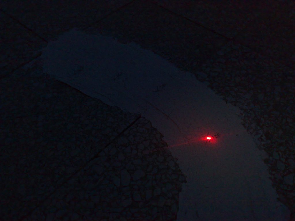
It is wonderful in the dark (the halo generated by the white LED is not very evident in the photo).
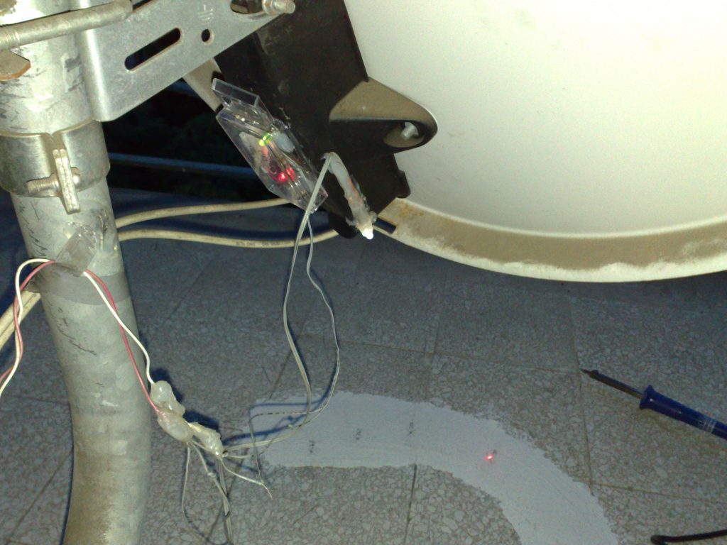
This is the final result we obtain. Note that the dish can rotate on the pole in the east-west direction and can change the elevation angle (point up, point down). It can not change the vertical position on the pole, as there is a bracket which doesn't let it to slide down (it can only rotate laterally by sliding on it). This is important because the laser dot has only two degrees of freedom (the position on the floor), so it can not work if you move the dish along three degrees of freedom. Be sure to have this bracket really well fixed before marking your satellite positions on the floor.
What is missing?
One thing I have not described is the power supply. I don't use the batteries, as I hate that they may be out of charge when I need them. You can, in theory, just use a low cost DC power adaptor with the right voltage. But it will not work! You will burn your laser! It happened to me more than once and it is really annoying if you have to rebuild everything (consider the old marks will be probably useless as the glueing positions will not be exactly the same). I solved the problem this way. I measured the exact voltage of the batteries and built an electronic stabilized power adapter with that voltage. It sounds difficult to do, but it actually means I use a low cost power adapter with a higher voltage (let's say 6V or 7.5V) and then a small circuit (3 resistors and a transistor) to reduce the voltage to the correct value (around 4V if I remember correctly). I will document how to build the circuit if someone is interested (anyone can do that if he can use a soldering iron).